Blog
Wire Length Measurement Guide
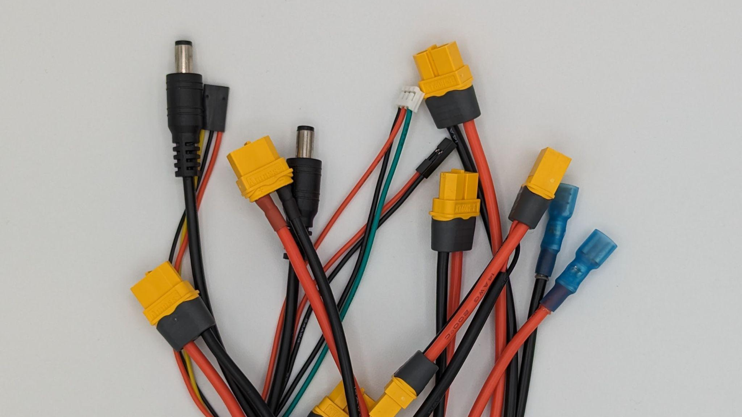
One of the most common problems leading to wire harness redesign is a harness that is not the right length, either too short to reach all terminals or too long to be routed cleanly. This article explains how MiniProto measures wire lengths for harnesses designed using the harness design tool (custom drawings provided will be interpreted as noted in the drawing).
General Guidelines
-
Wire lengths are measured along the exposed length of wire.
-
Any part of a wire covered by a connector, protector, or heatshrink (even if transparent) is treated as unexposed and therefore not part of the wire length.
-
Splices generally measure approximately .50-.75in (12.7-19.1mm) of exposed copper with .25in (6.4mm) of heat shrink overlap with either side of the wire insulation.
-
If in doubt, a first article photo may be requested at no cost to the customer. Email support@miniproto.com to request.
Simple Harness Examples
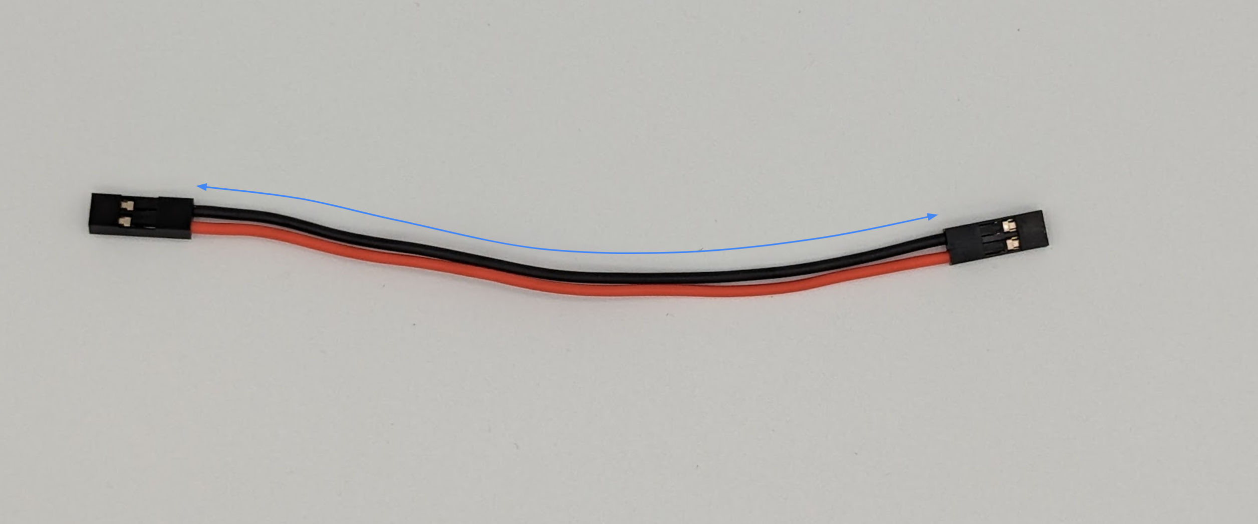
In this simplest of examples, the black wire length is measured along all exposed length of wire between each connector.
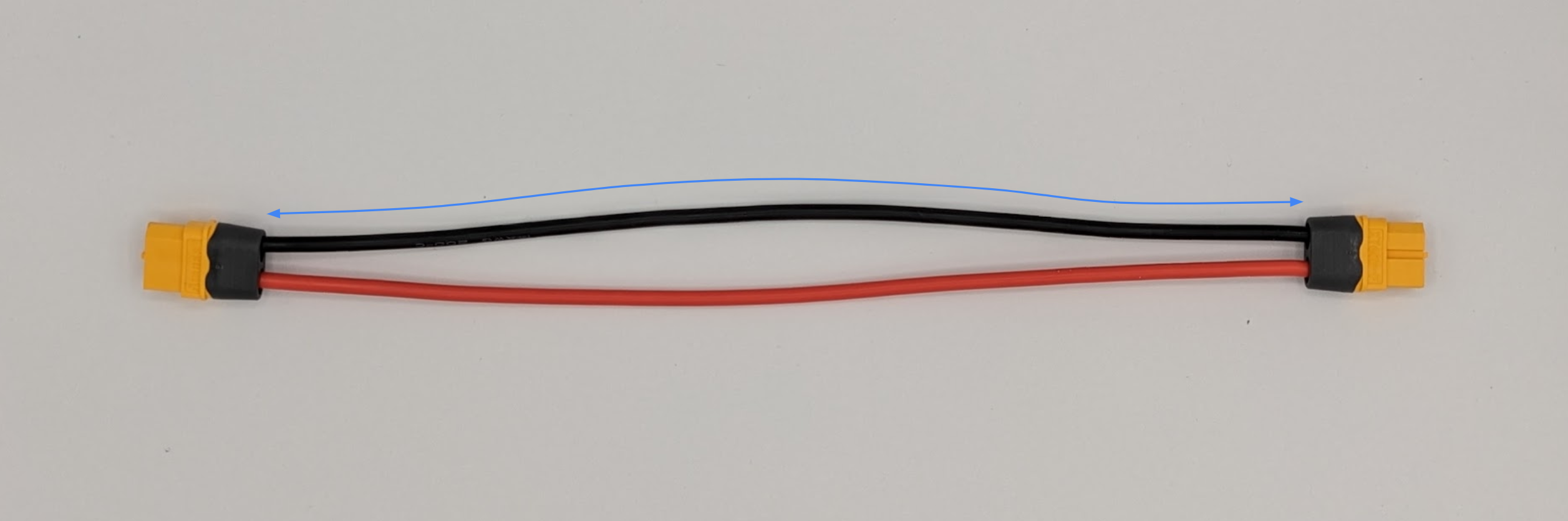
Some connectors, such as this XT60, have optional snap-in protectors. Since these cover the wire, the length is measured from where the wire exits the protector.
Heat Shrink Examples
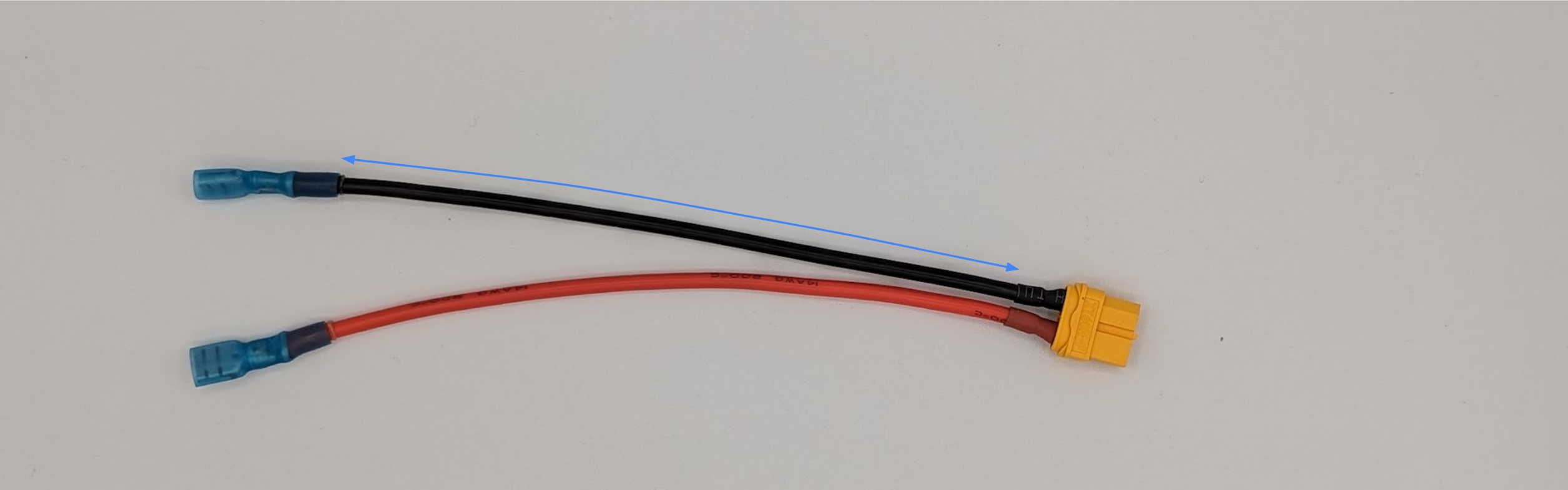
An unprotected XT-60 harness still requires heat shrink, which is applied per guideline 3. A Molex Perma-Seal terminal on the other end, though transparent, still covers the wire, so the length is measured from the end of the integrated heat shrink as shown.
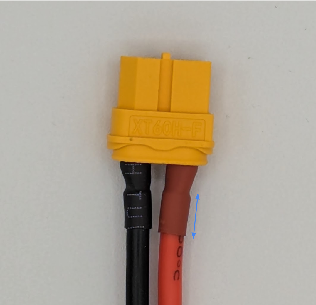
The heatshrink applied per guideline 3 measures approximately .25in (6.4mm) here.
Spliced Examples
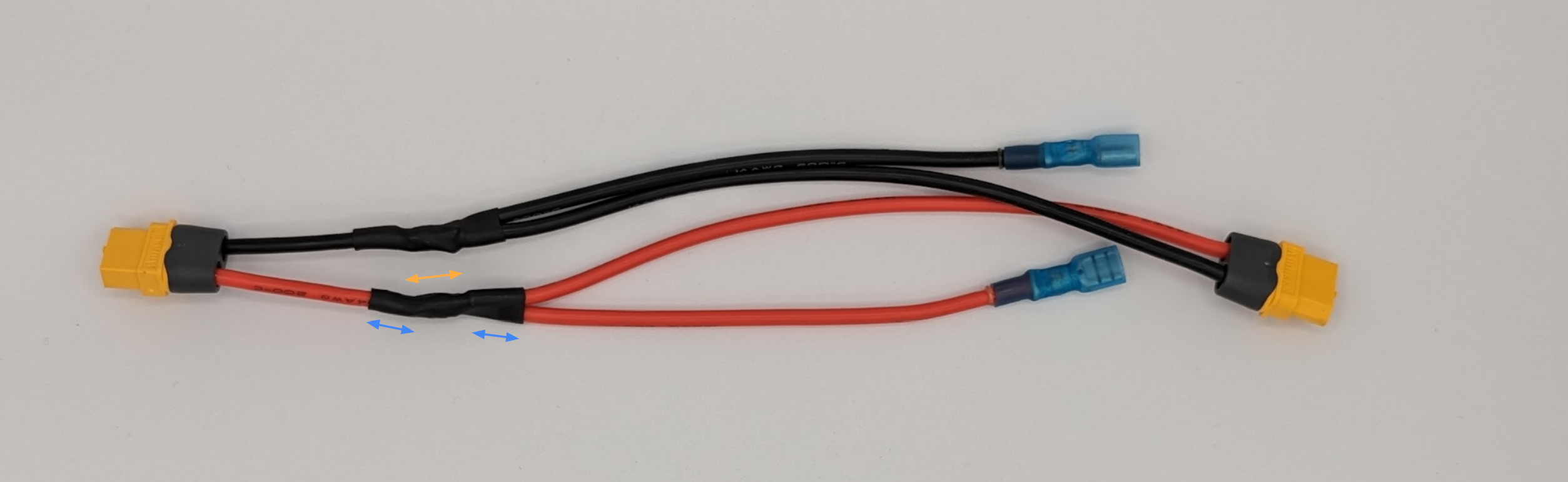
In a more complex example, the two blue dimensions measure approximately .25in (6.4mm) while the orange dimension measures approximately .50in (12.7mm).
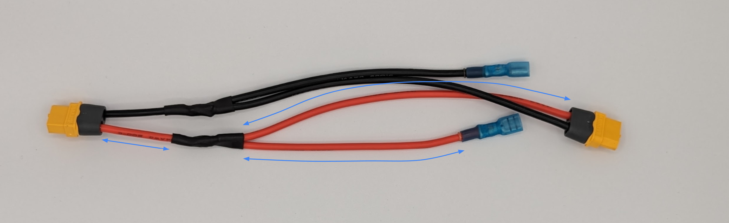
The red wire lengths would therefore be measured as above.
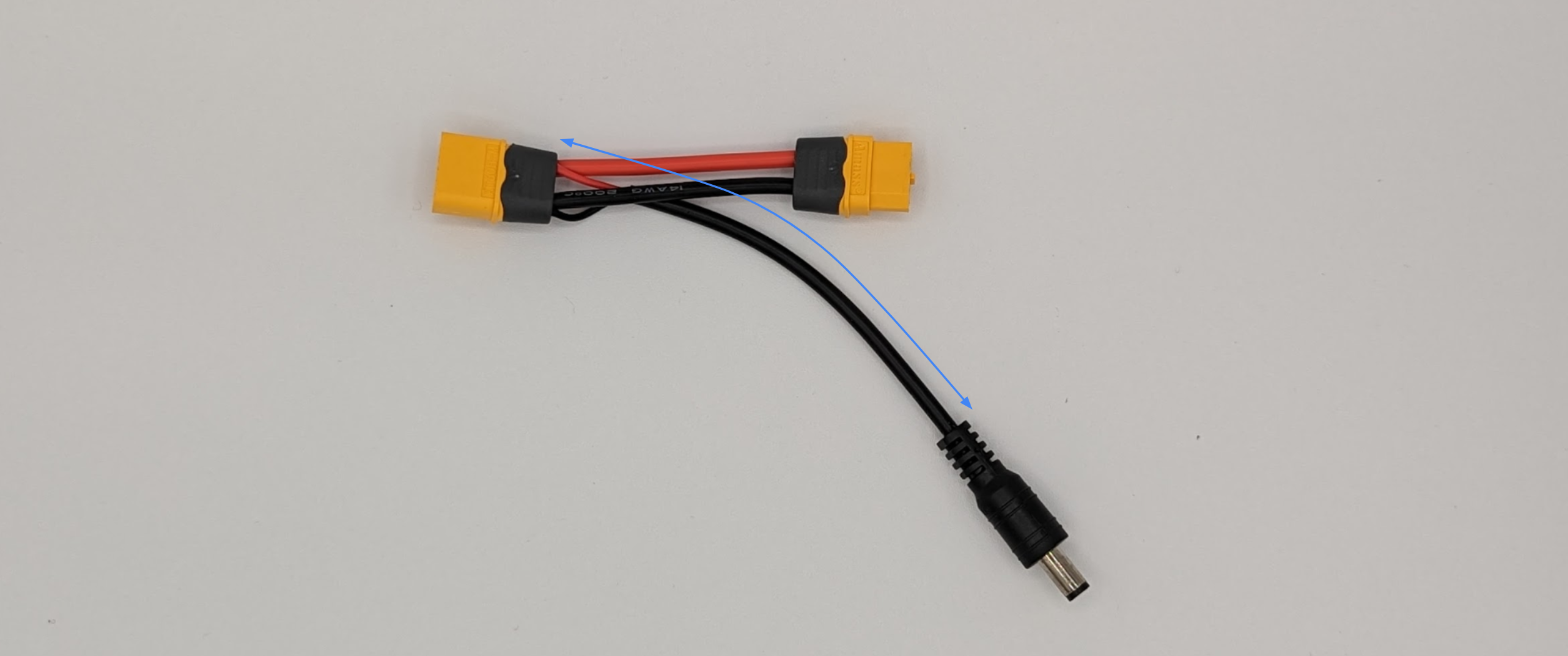
This example includes a barrel connector with integrated strain relief and a wrapped two conductor cable. The length is measured as shown as this translates to the “exposed length of wire” principle.
Additional Notes
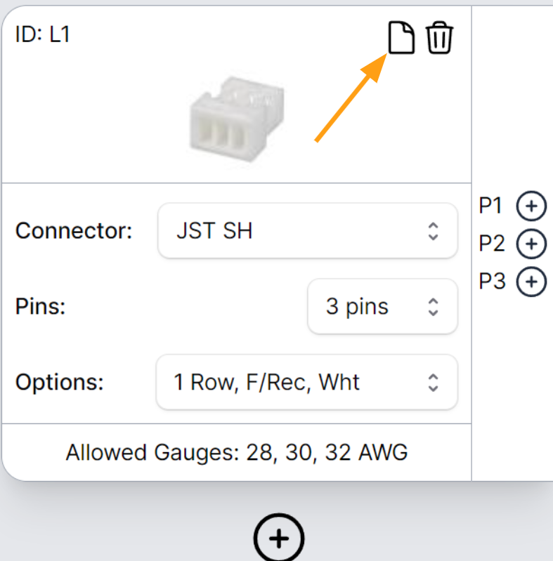
Unfortunately, it can often be difficult to determine the overall length of the harness (including the connectors). MiniProto provides the best available datasheet for each connector in the online configuration tool by clicking the button shown below.** **
If any questions remain, please do not hesitate to contact support@miniproto.com with any questions. We are happy to provide assistance, measurements, pictures, and even fully labeled first article inspection photos on request.
Related Links
Related Posts
Connector Keying and Polarization, and Why They Matter
What connector keying and polarization do, how Deutsch and MIL-DTL-38999 handle them, and why to plan keying early in your design.
Crimp vs. Solder: Choosing the Right Wire Termination
When to crimp, when to solder, and why crimped contacts are the default in wire harnesses. Practical guidance from the shop floor.
Shielding Basics: A Guide to Reducing Electromagnetic Interference
This article explains how EMI shielding mitigates electromagnetic interference through reflection and conduction to ground. It covers shielding strategies for magnetic and electric fields, compares cable shielding types (non-shielded, foil, braided, and combination), and discusses shielding effectiveness in decibels (dB). Giving a basic understanding of these aspects helps engineers select the right shielded cable for their custom harness applications.
Need a custom harness?
Newsletter
Stay Wired with MiniProto.
Join our community and be the first to know about the latest in wire harness prototyping. Get exclusive insights, tips, and updates delivered straight to your inbox.
- Latest Prototyping Trends
- Stay ahead in the field with our articles on MiniProto updates, new technologies, design tips, and industry insights.
- No Spam, Only Value
- We respect your inbox. Receive only the most relevant updates and offers, without the clutter of unwanted emails.